SP3 - Pool Entry/Access
| Issue Date | Effective Date | Version |
|---|---|---|
| 19/09/2017 | 01/01/2018 | 3.0 |
Purpose
To establish guidelines for the safe design of swimming pool entry and exit
Access to the Pool Tank
Access to a pool tank may be provided by a range of means including but not limited to:
- Steps and Ladders
- Fixed or moveable ramps
- Zero Depth Entry
- Lifts
The methods should provide easy and safe entry to an exit from the water. Fewer entry points may be needed where the pool edge is of deck level type since many swimmers find it easier to enter and leave this type of pool directly from the poolside.
Pool entry/exit steps and handrails above, at or below the surface of the water should not protrude into or over lap swimming lanes where they may present a hazard to swimmers.
The most appropriate arrangements for access are as follows:
- Main pools entry/exit climb outs and steps should be provided on both sides of each end of the pool approximately 1m from the pool tank wall.
- Longer (50m) pools these should be provided at the midpoint of each side.
- Irregular shaped leisure pools adequate entry and exit areas should be provided at regular intervals (i.e. 15m).
- Beach entries should be flush with pool concourse or wet deck, and where not flush a contrasting colour band and appropriate signage should be used to warn the public. Beach entry areas should be visually distinguishable from the pool floor.
Steps and Ladders
Steps and ladders providing access to the pool should be as follows:
- Designed to ensure that finger, limb and head traps are not created, either between the treads or the tank walls, or between the hand rails or the tank walls.
- The vertical (rise) and horizontal (tread) edges of steps should be a contrasting colour to aid entry and exit from the pool.
- Steps should have a rise and tread conforming to the Building Code of Australia and have slip-resistive and non-abrasive surface finishes.
- Steps providing access to learner or toddler pools should have wider steps (300mm minimum) with shallow risers (150mm minimum) in dimensions.
- Tactile Ground Surface Indicators should be installed in accordance with AS 1428.4.1:2009.
Fixed or Moveable Ramps
A fixed or moveable ramp should:
- Have a slip-resistant surface conforming to the recommendations of Standards Australia Handbook “HB 197 - An Introductory Guide to the Slip Resistance of Pedestrian Surface Materials” and AS 4586-2013
- Have a maximum gradient of 1:14; and
- Have handrails complying with the requirements for ramps in AS 1428.1-2009, installed on both sides of the ramp; and
- Have kerbs in accordance with the requirements for ramps in AS 1428.1-2009; and
- Extend to a depth of not less than 900 mm and not more than 1100 mm below the stationary water level; and
- Have landings in accordance with the requirements for ramps in AS 1428.1-2009, with a landing located at the bottom and top of each ramp and a landing should be located at a level between 900 mm and 1100 m below the stationary water level
N.B Where starting blocks are present the minimum depth of water should be 1.35m extending from 1000mm to at least 6000mm from the end wall. Ramps should not be located within the region where the ramp ends at a depth greater than 1100mm.
Zero Depth Entry
A zero depth entry should have:
- A slip-resistant surface; and
- A maximum gradient of 1:14; and
- A single handrail complying with the requirements for handrails in AS 1428.1-2009, from the top of the entry point continuous to the bottom level area; and
- A level area:
- 1500 mm long for the width of the zero depth entry at the entry point and;
- Located at the bottom of the zero depth entry at a level between 900 mm and 1100 mm below the stationary water level.
N.B. Where a beach entry is not flush a contrasting colour band and uneven surfaces signage should be displayed
N.B This may not be possible in some Zero Depth Entry pools where the handrail itself poses a greater risk to other swimmers.
Handrails
Handrails should be provided at all entry/exit steps as follows:
- Designed to ensure that finger, limb and head traps are not created, either between the treads or the tank walls, or between the hand rails or the tank walls and do not present a hazard during aquatic activities such as tumble turns and play.
- Barrier rails should be provided to prevent swimmers from jumping from the concourse on to steps or ramps.
- Handrails should be provided on both sides of a ramp.
- Steps which may be frequented by aged or frail persons should be provided with handrails on both sides in accordance with AS 1428.1.
- For extra wide steps, it is recommended that handrails be provided at intervals of between 2.0m to 3.0m.
Platform Swimming Pool Lift
A platform swimming pool lift should be:
- Capable of being operated from the swimming pool surround, within the swimming pool, and on the platform; and
- Located where the water depth is not more than 1 300 mm; and
- Designed to withstand a weight capacity of not less than 160 kg and be capable of sustaining a static load of not less than 1.5 times the rated load.
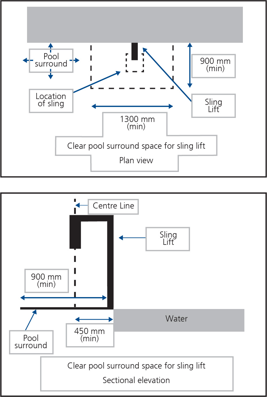
Sling-Style Swimming Pool Lift
A sling lift should comply with the following:
- A sling lift should be located where the water depth is not more than 1 300 mm;
- When the sling is in the raised position and in the transfer position, the centreline of the sling should be located over the swimming pool surround and not less than 450 mm from the swimming pool edge;
- The surface of the swimming pool surround between the centreline of the sling and the swimming pool edge should have a gradient of not more than 1:50 and should be slip-resistant;
- A clear space:
- not less than 900 mm x 1 300 mm; and
- with a gradient of not more than 1:50; and
- a slip-resistant surface; and
- located so that the centreline of the space is directly below the lifting point for the sling;
- should be provided on the swimming pool surround parallel with the swimming pool edge on the side remote from the water
- A sling lift should be capable of being operated from the swimming pool
- The sling should be designed so that it will submerge to a water depth of not less than 500 mm below the stationary water level;
- A sling lift should be designed to withstand a weight of not less than 136 kg and be capable of sustaining a static load not less than 1.5 times the rated load.
Aquatic Wheelchair
An aquatic wheelchair should comply with the following:
- The height of the top surface of the seat should be not less than 430 mm;
- The seat width should not be not less than 480 mm;
- A footrest should be provided;
- Armrests should be located on both sides of the seat and should be capable of being moved away from the side of the chair to allow a person to transfer on and off the seat.
References
- Disability (Access to premises-Building) Standards 2010
- Australian Standards Handbook HB 197 - 1999; An Introductory Guide to the Slip Resistance of Pedestrian Surface Materials
- AS 1428.1 - 2009; Design for access and mobility Part 1: General requirements for access - New building work.
- Building Code of Australia - 2006. Australian Building Code Board.
- Managing Health and Safety in Swimming Pools
Previous Versions
- FD5 Design of Pool Access Issue 2, November 2007
- FD18 Design for Special Needs Populations, Issue 2, 1 November 2007


